81. An amplifier using BJT has two identical stages each having a lower cut-off (3 dB) frequency of 64 Hz due to coupling capacitor. The emitter bypass capacitor also provides a lower cut-off (3 dB) frequency due to emitter degeneration alone of 64 Hz. The lower (3 dB) frequency of the overall amplifier is nearly
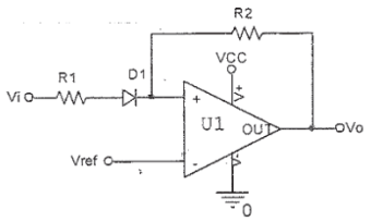
82. What would be the output of the following circuit, if a positive going unipolar pulse with an amplitude greater than Vref, is applied at the input?


83. A high gain OpAmp has Rf = 105Ω & Ri = 103Ω. The correct statements is:
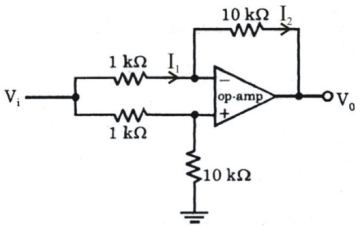
84. The V0 of the op-amp circuit shown in the given figure is


85. The main advantage in using three op-amp instrumentation amplifier over a single stage op-amp differential amplifier lies in
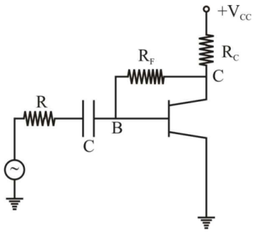
86. In the circuit shown in the given figure, RF provides


87. An n-channel enhancement mode MOSFET is biased at VGS > VTH and VDS > (VGS - VTH), where VGS is the gate-to-source voltage. VDS is the drain-to-source voltage and VTH is the threshold voltage. Considering channel length modulation effect be significant, the MOSFET behaves as a
88. For an OPAMP, unity gain frequency is 106 if gain is 20, What is the Bandwidth of the op-amp . . . . . . . .
89. The cross-over distortion in class B push-pull amplifier is eliminated by
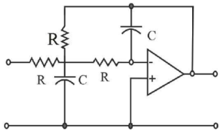
90. The transfer function of a second order low pass filter shown in Figure is


Read More Section(Analog Electronics)
Each Section contains maximum 100 MCQs question on Analog Electronics. To get more questions visit other sections.
