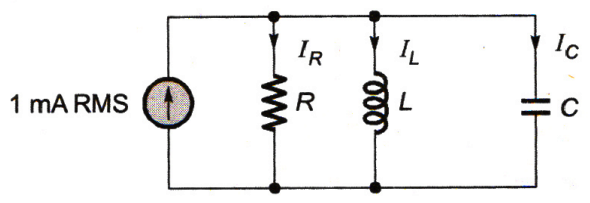
41. The parallel RLC circuit shown in figure is in resonance. In this circuit

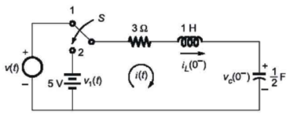
42. In the figure, the switch is thrown from position 1 to 2 at time t = 0. Just before the switch is thrown, the initial conditions are iL (0-) = 2 A, VC (0-) = 2 V. What is the current i(t) after switching action?

43. The current through a series RL circuit $$\frac{1}{4}{{\text{e}}^{ - {\text{t}}/2}}$$ when excited by a unit impulse voltage. The values of R and L are respectively
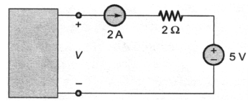
44. The voltage V in figure is always equal to

45. Consider the circuit shown in the figure with input V(t) in volts. The sinusoidal steady state current I(t) flowing through the circuit is shown graphically (where t is in seconds). The circuit element Z can be . . . . . . . .


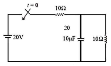
46. In the figure given below, the initial capacitor voltage is zero. Then after switch is closed at t = 0 , Calculate the final steady state voltage across the circuit:

47. Electrolytic Capacitors are generally made of
48. The length of a certain conductor of resistance 100 Ω is doubled and its cross-sectional area is halved. Its new resistance is:
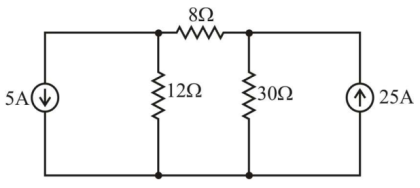
49. Find the current I in figure below:

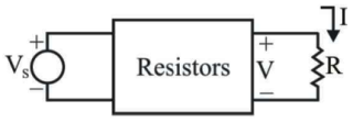
50. In the circuit shown, for different values of R, the values of V and I are given, other elements remaining the same
When R = ∞, V = 5V
When R = 0, I = 2.5 A
When R = 3 Ω, the value of V is given by
When R = ∞, V = 5V
When R = 0, I = 2.5 A
When R = 3 Ω, the value of V is given by

Read More Section(Network Theory and Analysis)
Each Section contains maximum 100 MCQs question on Network Theory and Analysis. To get more questions visit other sections.
