71. The time rate of change of a current passed through a 1 mH inductor is 2 mA/s. This means that the voltage across the inductor is:
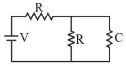
72. A circuit consisting of two resistors, a capacitor and a battery is shown in the figure. In the steady state, the voltage across the capacitor would be:


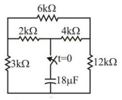
73. A 18 µf capacitor holding charge of Q coulomb is connected to the circuit at time t = 0 sec.
The time at which the capacitor will be discharged to approximately Q/2.72 coulombs.

The time at which the capacitor will be discharged to approximately Q/2.72 coulombs.

74. A network has 10 nodes and 17 branches. The number of different node pair voltage would be
75. The ideal transformer CANNOT be described by:
76. For the given circuit, the currents i1 and i3 are


77. A buffer amplifier has a gain of
78. A certain network consists of two ideal voltage sources and a large number of ideal resistors. The power consumed in one of the resistor is 4 W when either of the two sources is active and the other is replaced by short-circuit. The power consumed by the same resistor, when both the sources are simultaneously active would be
79. Two coils X of 1000 turns and Y of 2000 turns are placed such that 60% of the flux produced by coil X links coil Y. A current of 1 A in coil X produces 0.1 mWb flux. The mutual inductance between the coils is
80. In the network shown in the figure, the switch had remained closed for a long time on the 10 V source side. At time t = 0, it is changed to the 12 V side, then after one time constant, the voltage across 5 Ω in the circuit will be


Read More Section(Network Theory and Analysis)
Each Section contains maximum 100 MCQs question on Network Theory and Analysis. To get more questions visit other sections.
