
ExamVeda
Login
Home
41
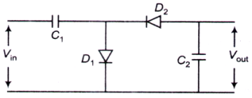
A sinusoidal input voltage Vin of frequency ω is fed to the circuit shown in the figure, where C1 ≫ C2. If Vm is the peak value of the input voltage, then output voltage (Vout) is
Electronics mcq question image
Discuss
Answer & Solution
Answer: Option A
No explanation is given for this question. Let's Discuss on Board
42
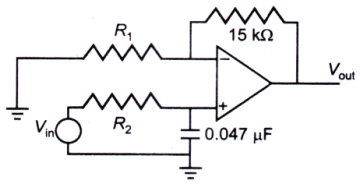
The low-pass active filter shown in the figure has a cut-off frequency of 2 kHz and a pass band gain of 1.5. The values of the resistors are
Electronics mcq question image
Discuss
Answer & Solution
Answer: Option D
No explanation is given for this question. Let's Discuss on Board
43
The largest analog output voltage from a 6-bit Digital to Analog Converter (DAC) which produces 1.0 V output for a digital input of 010100, is
Discuss
Answer & Solution
Answer: Option C
No explanation is given for this question. Let's Discuss on Board
44
Which one of the sets of values given below does not satisfy the Boolean relation R = PQ' (where, Q' denotes not Q)?
Discuss
Answer & Solution
Answer: Option B
No explanation is given for this question. Let's Discuss on Board
45
In an n-p-n transistor, the leakage current consists of
Discuss
Answer & Solution
Answer: Option C
No explanation is given for this question. Let's Discuss on Board
46
A bipolar junction transistor with one junction forward biased and either the collector or emitter open, operates in the
Discuss
Answer & Solution
Answer: Option C
No explanation is given for this question. Let's Discuss on Board
47
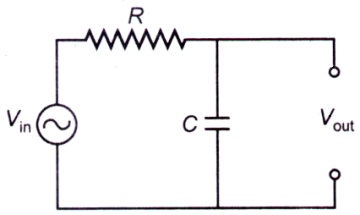
The circuit shown in the figure can be used as a
Electronics mcq question image
Discuss
Answer & Solution
Answer: Option D
No explanation is given for this question. Let's Discuss on Board
48
A field effect transistor is a
Discuss
Answer & Solution
Answer: Option A
No explanation is given for this question. Let's Discuss on Board
49
In a typical n-p-n transistor, the doping concentrations in emitter, base and collector regions are CE, CB and CC respectively. These satisfy the relation,
Discuss
Answer & Solution
Answer: Option A
No explanation is given for this question. Let's Discuss on Board
50
The simplest logic gate circuit corresponding to the Boolean expression, Y = P + PQ is
Discuss
Answer & Solution
Answer: Option B
No explanation is given for this question. Let's Discuss on Board