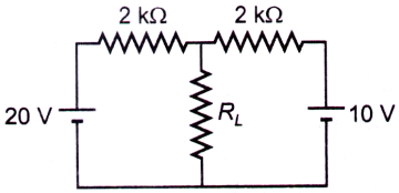
In the circuit shown in the figure, the Thevenin voltage VTh and Thevenin resistance RTh as seen by the load resistance RL (= 1 k$$\Omega $$) are respectively

A. 15 V, 1 k$$\Omega $$
B. 30 V, 4 k$$\Omega $$
C. 20 V, 2 k$$\Omega $$
D. 10 V, 5 k$$\Omega $$
Answer: Option A
Related Questions on Electronics
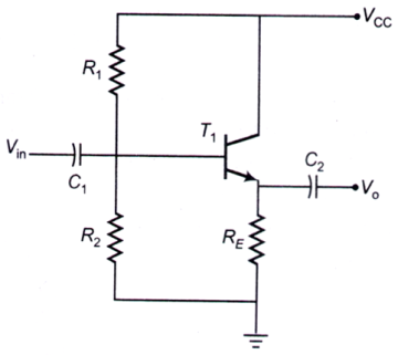
A. is a common-emitter amplifier
B. uses a p-n-p transistor
C. is an oscillator
D. has a voltage gain less than one
A. 1 AND gate
B. 2 AND gates
C. 1 OR gate
D. 2 OR gates
A. the gain decreases by 10 times
B. the output resistance increases by 10 times
C. the fH increases by 100 times
D. the input resistance decreases by 100 times
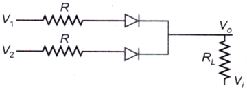
The following circuit (where, RL ≫ R) performs the operation of
A. OR gate for a negative logic system
B. NAND gate for a negative logic system
C. AND gate for a positive logic system
D. AND gate for a negative logic system


Join The Discussion