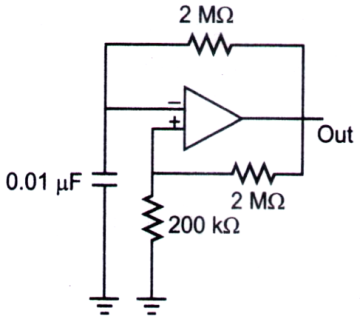
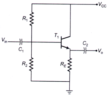
1. 
The circuit shown above

The circuit shown above
2. The Boolean expression $$B\left( {A + B} \right) + A\left( {\overline B + A} \right)$$ can be realized using minimum number of
3. An amplifier of gain 1000 is made into a feedback amplifier by feeding 9.9% of its output voltage in series with the input opposing. If fL = 20 Hz and fH = 200 kHz for the amplifier without feedback, then due to the feedback
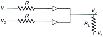
4. The following circuit (where, RL ≫ R) performs the operation of

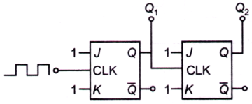
5. In the circuit shown, the ports Q1 and Q2 are in the states Q1 = 1, Q2 = 0. The circuit is now subjected to two complete clock pulses. The state of these ports now becomes

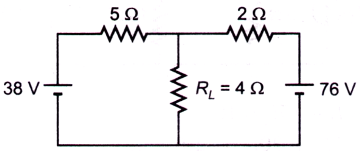
6. For the circuit shown below, the potential difference (in volt) across RL is

7. An AC voltage of 220 V(rms) is applied to the primary of a 10 : 1 step-down transformer. The secondary of the transformer is centre tapped and connected to a full-wave rectifier with a load resistance. The DC voltage appearing the load is
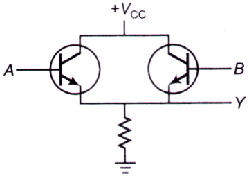
8. The circuit shown in the figure below function as

9. A bistable multivibrator with a saturation voltage ±5 V is shown in the diagram. The positive and negative thresholds at the inverting terminal for which the multivibrator will switch to the other state, are
