
?
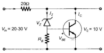
The transistor shunt regulator shown in the figure has a regulated output voltage of 10 V, when the input varies from 20 V to 30 V. The relevant parameters for the zener diode and the transistor are: VZ = 9.5, VBE = 0.5 V, β = 99. Neglect the current through RB. Then the maximum power dissipated in the zener diode (PZ) and the transistor (PT) are
Competitive Exams
Aptitude
English
Verbal Reasoning
Non Verbal Reasoning
General Knowledge(GK)
General Science(GS)
Data Interpretation(DI)
Banking Awareness
Current Affairs
Computer & Programming
Computer Fundamentals
Networking
SQL
Database
C Programming
C++ Programming
Java
Python
Other Subjects
Commerce
Management
Law
Political Science
Psychology
Agriculture

Join the Discussion
Login to post a comment or share your explanation.
Login