
ExamVeda
Login
Home
71
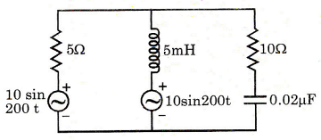
Which one of the following theorems can be conveniently used to calculate the power consumed by the 10 Ω resistor in the network shown in the figure below?
Network Theory and Analysis mcq question image
Discuss
Answer & Solution
Answer: Option D
No explanation is given for this question. Let's Discuss on Board
72
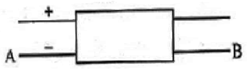
With 10 V DC connected at port A in the linear nonreciprocal two port network shown below, the following were observed
1. 1 Ω connected at port B draws a current of 3 A
2. 2.5 Ω connected at port B draws a current of 2 A
The current drawn by 7 Ω connected at port B
Network Theory and Analysis mcq question image
Discuss
Answer & Solution
Answer: Option C
No explanation is given for this question. Let's Discuss on Board
73
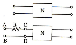
The open circuit parameters of 2-port network N shown in the figure, are \[\left[ {\begin{array}{*{20}{c}} {{{\text{Z}}_{11}}}&{{{\text{Z}}_{12}}} \\ {{{\text{Z}}_{21}}}&{{{\text{Z}}_{22}}} \end{array}} \right].\]   When the network is extended by a resistance R as shown in the figure, the input impedance of the network at points A, B will be
Network Theory and Analysis mcq question image
Discuss
Answer & Solution
Answer: Option D
No explanation is given for this question. Let's Discuss on Board
74
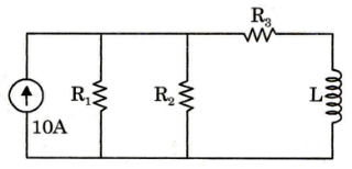
The time constant of the network shown in the given figure is given by
Network Theory and Analysis mcq question image
Discuss
Answer & Solution
Answer: Option A
No explanation is given for this question. Let's Discuss on Board
75
For non-inverting adder, which theorem is applicable to determine the expression for output voltage?
Discuss
Answer & Solution
Answer: Option D
No explanation is given for this question. Let's Discuss on Board
76
For a certain load, the true power is 100 W and the reactive power is 100 VAR. What is the apparent power?
Discuss
Answer & Solution
Answer: Option B
No explanation is given for this question. Let's Discuss on Board
77
What power absorbed by R
Network Theory and Analysis mcq question image
Discuss
Answer & Solution
Answer: Option B
No explanation is given for this question. Let's Discuss on Board
78
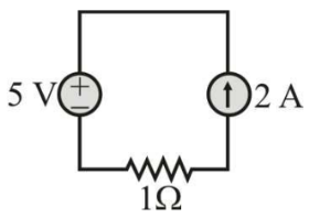
For the circuit shown in figure
Network Theory and Analysis mcq question image
Discuss
Answer & Solution
Answer: Option B
No explanation is given for this question. Let's Discuss on Board
79
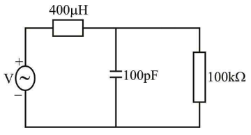
R and C are connected in parallel across a sinusoidal voltage source of 240 V. If the currents through the source and the capacitor are 5 A and 4 A respectively, what is the value of R?
Discuss
Answer & Solution
Answer: Option C
No explanation is given for this question. Let's Discuss on Board
80
For the circuit shown in the below figure, what is the natural frequency?
Network Theory and Analysis mcq question image
Discuss
Answer & Solution
Answer: Option D
No explanation is given for this question. Let's Discuss on Board