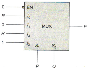
The figure below shows a multiplexer where S1 and S0 are the select lines. I0 to I3 are the input data lines, EN is the enable line, and F(P, Q, R) is the output. F is

A. $$\overline {\text{Q}} + {\text{PR}}$$
B. $${\text{P}} + {\text{Q}}\overline {\text{R}} $$
C. $${\text{PQ}} + \overline {\text{Q}} {\text{R}}$$
D. $${\text{P}}\overline {\text{Q}} {\text{R}} + \overline {\text{P}} {\text{Q}}$$
Answer: Option C
Related Questions on Digital Electronics
In which of the following base systems is 123 not a valid number?
A. Base 10
B. Base 16
C. Base 8
D. Base 3

Join The Discussion