11. The binary number 101 represents:
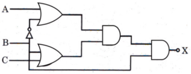
12. The output X of the logic circuit shown in the figure is


13. A digital frequency converter can be converted to DVM by addition of a suitable
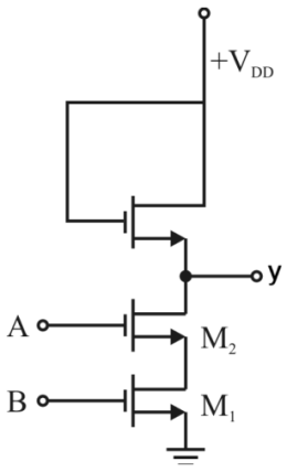
14. The circuit shown in figure is


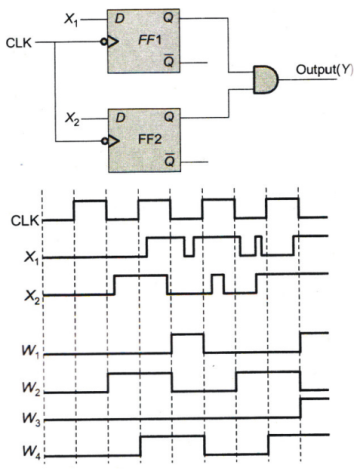
15. In the circuit shown, choose the correct timing diagram of the output (Y) from the given waveforms W1, W2, W3 and W4.


16. Which of the following statements about the K-maps is INCORRECT?
17. If (432)5 = (x)7, then the value of x is
18. Given (125)R = (203)5. The value of radix R will be
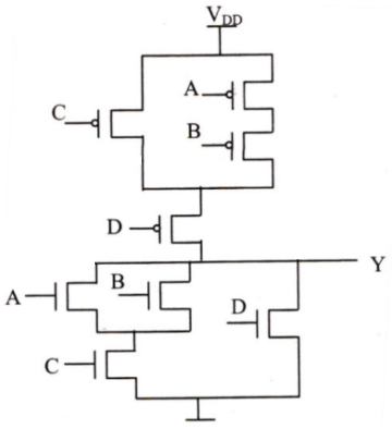
19. Find Y


20. A 4-bit presetable UP counter has preset input 0101. The preset operation takes place as soon as the counter reaches 1111. The modulus of the counter is
Read More Section(Digital Electronics)
Each Section contains maximum 100 MCQs question on Digital Electronics. To get more questions visit other sections.
