61. A number is expressed in binary two's complement as 10011. Its decimal equivalent value is
62. Which one of the following is not a characteristic of RTL logic families?
63. Which of the following are universal gates?
1. AND
2. NAND
3. OR
4. NOR
5. NOT
1. AND
2. NAND
3. OR
4. NOR
5. NOT
64. Combinational circuit
65. Two D-flip-flops, as shown below, are to be connected as a synchronous counter that goes through the following Q1Q0 sequence
00 → 01 → 11 → 10 → 00 → . . . . .
The inputs D0 and D1 respectively should be connected as

00 → 01 → 11 → 10 → 00 → . . . . .
The inputs D0 and D1 respectively should be connected as

66. The Boolean expression $$\left( {{\text{X}} + {\text{Y}}} \right)\left( {{\text{X}} + \overline {\text{Y}} } \right) + \overline {\left( {\overline {\text{X}} \overline {\text{Y}} } \right) + \overline {\text{X}} } $$ simplifies to
67. Given VOH = 4 V, VIH = 3.2 V, VIL = 2 V, VOL = 1.5 V, find noise margin?
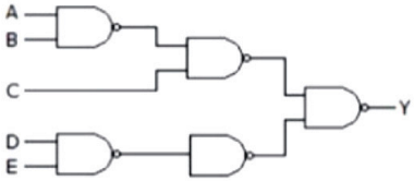
68. In the above diagram, find out the correct expression of Y.


69. The simplified form of the Boolean expression AB + A(B + C) + B(B + C) is given by
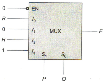
70. The figure below shows a multiplexer where S1 and S0 are the select lines. I0 to I3 are the input data lines, EN is the enable line, and F(P, Q, R) is the output. F is


Read More Section(Digital Electronics)
Each Section contains maximum 100 MCQs question on Digital Electronics. To get more questions visit other sections.
