ExamVeda
Login
Home
21
An energy source forces a constant current of 5 ampere for 4 sec to flow through a light bulb. If 3 kJ is give in terms of light energy, the voltage drop across the bulb is . . . . . . . .
Discuss
Answer & Solution
Answer: Option A
No explanation is given for this question. Let's Discuss on Board
22
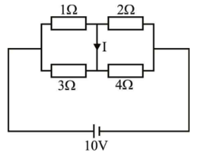
In the circuit shown in the given figure, current I is
Network Theory and Analysis mcq question image
Discuss
Answer & Solution
Answer: Option D
No explanation is given for this question. Let's Discuss on Board
23
In the lattice network, find the value of R for the maximum power transfer to the load
Network Theory and Analysis mcq question image
Discuss
Answer & Solution
Answer: Option B
No explanation is given for this question. Let's Discuss on Board
24
The reactance of a 1 Henry inductor at 50 Hz will be
Discuss
Answer & Solution
Answer: Option A
No explanation is given for this question. Let's Discuss on Board
25
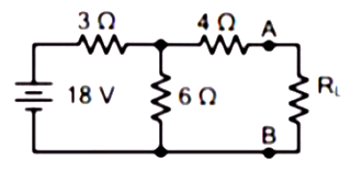
Calculate the value of RL so that the power transfer in the given circuit will be maximum.
Network Theory and Analysis mcq question image
Discuss
Answer & Solution
Answer: Option A
No explanation is given for this question. Let's Discuss on Board
26
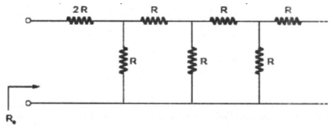
Find Re in k Ω (Assume R = 1 Ω)
Network Theory and Analysis mcq question image
Discuss
Answer & Solution
Answer: Option B
No explanation is given for this question. Let's Discuss on Board
27
For the circuit shown in the given figure, when the switch is at position A, the current i(t) = Isin(ωt + 30°) A. When switch is moved to position B at time t = 0, the power dissipated at the switching instant in the resistor R remains unchanged
The value of I and the element X would respectively, be
Network Theory and Analysis mcq question image
Discuss
Answer & Solution
Answer: Option D
No explanation is given for this question. Let's Discuss on Board
28
Unit of density is
Discuss
Answer & Solution
Answer: Option A
No explanation is given for this question. Let's Discuss on Board
29
The current I in the circuit shown is
Network Theory and Analysis mcq question image
Discuss
Answer & Solution
Answer: Option A
No explanation is given for this question. Let's Discuss on Board
30
The circuit shown in the figure is used to charge the capacitor C alternately from two current sources as indicated. The switches S1 and S2 are mechanically coupled and connected as follows.
For 2nT ≤ t < (2n + 1)T, (n = 0, 1, 2 . . .) S1 to P1 and S2 to P2.
For (2n + 1)T ≤ t < (2n + 2)T, (n = 0, 1, 2 . . .) S1 to Q1 and S2 to Q2.
Assume that the capacitor has zero initial charge. Give that u(t) is a unit step function, the voltage VC(t) across the capacitor is given by
Discuss
Answer & Solution
Answer: Option C
No explanation is given for this question. Let's Discuss on Board