
?
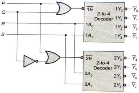
A 1-to-8 demultiplexer with data input Din, address inputs S0, S1, S2 (with S0 as the LSB) and $${\overline {\text{Y}} _0}$$ to $${\overline {\text{Y}} _7}$$ as the eight demultiplexed outputs, is to be designed using two 2-to-4 decoders (with enable input $$\overline {\text{E}} $$ and address inputs A0 and A1) as shown in the figure Din, S0, S1 and S2 are to be connected to P, Q, R and S, but not necessarily in this order. The respective input connections to P, Q, R and S terminals should be
Competitive Exams
Aptitude
English
Verbal Reasoning
Non Verbal Reasoning
General Knowledge(GK)
General Science(GS)
Data Interpretation(DI)
Banking Awareness
Current Affairs
Computer & Programming
Computer Fundamentals
Networking
SQL
Database
C Programming
C++ Programming
Java
Python
Other Subjects
Commerce
Management
Law
Political Science
Psychology
Agriculture

Join the Discussion
Login to post a comment or share your explanation.
Login